Brand Name: TSTY
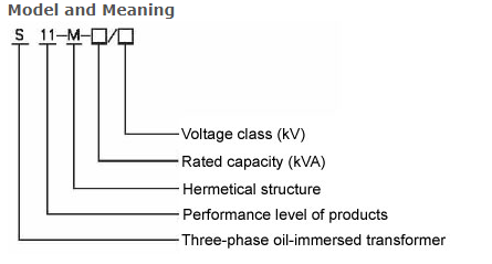
Model Number: S11
Phase: Three
Service Voltage: 6-35kV
Rated Capacity: 30-10000kVA
The products are in accordance with Chinese national GB standards and the international IEC standards.
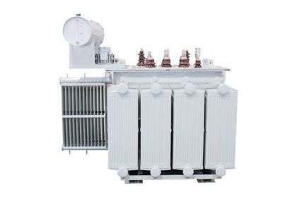
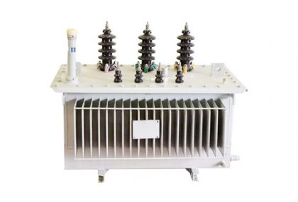
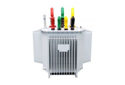
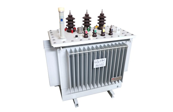
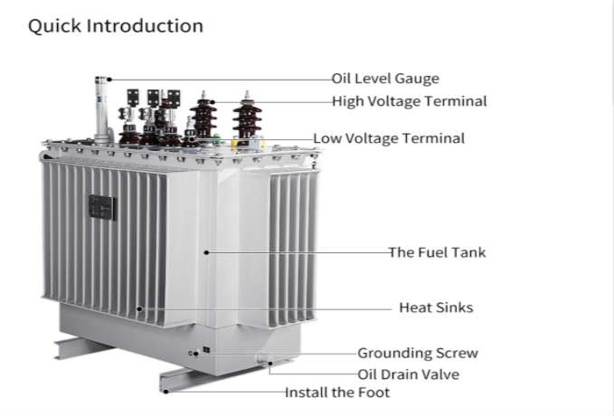
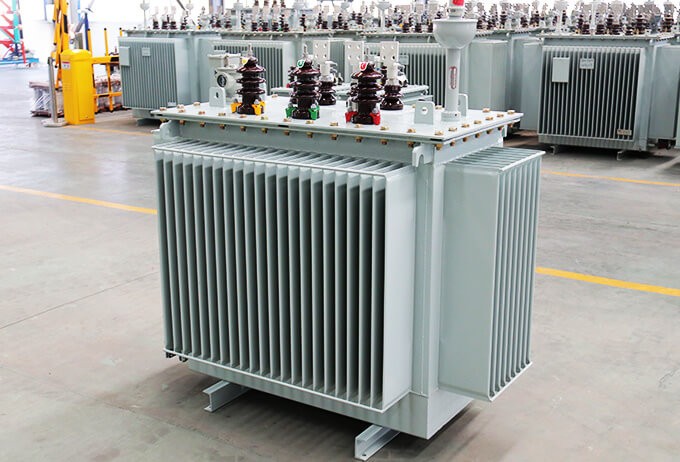
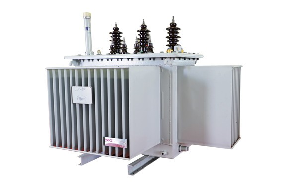
The company manufactures production of S11 - M series the whole sealing oil-immersed power transformer has the advantages of low loss, low noise, high efficiency, can obtain good energy saving effect and reduce pollution. Totally enclosed comparing with ordinary oil-immersed transformer, cancel the oil storage tank, the oil volume changed by corrugated tank elastic corrugated chips to automatically adjusting, transformer is isolated from the rest of the air, to prevent and slow the deterioration of oil and insulation aging, enhance the operation reliability.
Conditions of use
1. The highest temperature: + 40 ℃
2. The lowest temperature: -25 ℃
3. Altitude: < 4000 m
4. The highest monthly average relative humidity: 80% (20 ℃)
5. Installation location: without fire, explosion danger, serious foul, chemical corrosion, or violent vibration. Indoor And outdoor.
GB 1094 Power Transformer
GB/T 15164 Oil-immersed power transformer load guide
GB/T 6451 Three-phase oil-immersed power transformer technical parameters and requirements
IEC/60076
S11 type 6-11kV series main performance parameters of the products
| Type | Rated capacity (KVA) | Connection symbol | Voltage combination (KV) | No-load losses(W) | Load losses(W) | No- load current (%) | Short-circuit impedance (%) | ||
| H.V | Tapping range | L.V | |||||||
| S11 | 30 |
Yyn0 or Dyn11 |
6 6.3 10 10.5 11 | ±5% or ±2×2.5% | 0.4 | 100 | 600 | 2.3 | 4.0 |
| S11 | 50 | 130 | 870 | 2.0 | |||||
| S11 | 63 | 150 | 1040 | 1.9 | |||||
| S11 | 80 | 180 | 1250 | 1.9 | |||||
| S11 | 100 | 200 | 1500 | 1.8 | |||||
| S11 | 125 | 240 | 1800 | 1.7 | |||||
| S11 | 160 | 280 | 2200 | 1.6 | |||||
| S11 | 200 | 340 | 2600 | 1.5 | |||||
| S11 | 250 | 400 | 3050 | 1.4 | |||||
| S11 | 315 | 480 | 3650 | 1.4 | |||||
| S11 | 400 | 570 | 4300 | 1.3 | |||||
| S11 | 500 | 680 | 5100 | 1.2 | |||||
| S11 | 630 | 810 | 6200 | 1.1 | 4.5 | ||||
| S11 | 800 | 980 | 7500 | 1.0 | |||||
| S11 | 1000 | 1150 | 10300 | 1.0 | |||||
| S11 | 1250 | 1360 | 12800 | 0.9 | |||||
| S11 | 1600 | 1640 | 14500 | 0.8 | |||||
| S11 | 2000 | 2280 | 17820 | 0.6 | 5.0 | ||||
| S11 | 2500 | 2700 | 20700 | 0.6 | |||||
S11 type 15-22 kv series main performance parameters of the products
| Type | Rated capacity (KVA) | Connection symbol | Voltage combination(KV) | No-load losses(W) | Load losses(W) | No- load current(%) | Short-circuit impedance (%) | ||
| H.V | Tapping range | L.V | |||||||
| S11 | 30 | Dyn11 |
15 20 22 |
±5% or ±2×2.5% | 0.4 | 90 | 660 | 2.1 | 5.5 |
| S11 | 50 | 130 | 960 | 2 | |||||
| S11 | 63 | 150 | 1145 | 1.9 | |||||
| S11 | 80 | 180 | 1370 | 1.8 | |||||
| S11 | 100 | 200 | 1650 | 1.6 | |||||
| S11 | 125 | 240 | 1980 | 1.5 | |||||
| S11 | 160 | 290 | 2420 | 1.4 | |||||
| S11 | 200 | 330 | 2860 | 1.3 | |||||
| S11 | 250 | 400 | 3350 | 1.2 | |||||
| S11 | 315 | 480 | 4010 | 1.1 | |||||
| S11 | 400 | 570 | 4730 | 1 | |||||
| S11 | 500 | 680 | 5660 | 1 | |||||
| S11 | 630 | 810 | 6820 | 0.9 | 6 | ||||
| S11 | 800 | 980 | 8250 | 1.8 | |||||
| S11 | 1000 | 1150 | 11330 | 0.7 | |||||
| S11 | 1250 | 1350 | 13200 | 0.7 | |||||
| S11 | 1600 | 1630 | 15950 | 0.6 | |||||
2.Key component-coil
3.Key component-oil tank
Please Feel free to give your inquiry in the form below. We will reply you in 24 hours.